

close
Choose Your Site
Global
Social Media


How much usable fuel can an LNG storage tank actually hold? Its advertised volume tells only part of the story. Filling limits, liquid density, and retained inventory determine usable capacity. This guide explains the calculations and shows how to match storage capacity to demand.
Before choosing a formula, define what “capacity” means for your calculation. Geometric capacity describes the internal space available inside the liquid-containing vessel. Maximum liquid capacity describes the permitted liquid volume under specified conditions. Usable capacity describes the inventory available between defined upper and lower operating limits. These figures answer different questions, so they should remain separate throughout the worksheet. A purchasing team may need usable tonnes between deliveries. An engineer checking vessel dimensions may instead need geometric cubic meters. An operations team may want supply duration before the next scheduled delivery. Each result requires a different combination of inputs.
Next, establish the units and conditions supporting the calculation. Record whether volume refers to liquid LNG or natural gas at stated reference conditions. Specify the LNG density basis, including composition and liquid conditions where available. Also identify the approved maximum filling limit and minimum operating inventory. Use the same definitions when comparing different supplier proposals. A nominal volume alone cannot establish equivalent operating performance between two tanks. When assessing a mini cryogenic tank for LNG, request these capacity definitions alongside the quotation. This creates a clear starting point before calculations begin. It also prevents later confusion between total vessel space and fuel available for production.
Start from the inner vessel’s verified capacity whenever suitable documentation exists. Manufacturer drawings, capacity certificates, and approved technical records provide a stronger basis than external measurements. The relevant space belongs inside the liquid-containing boundary. It excludes the outer jacket and the insulation space surrounding the inner vessel. External piping, structural supports, and transport dimensions do not establish liquid capacity. For vessels containing significant internal structures, the documented capacity basis should explain relevant displacement allowances. This matters when a simple geometric estimate differs from the manufacturer’s stated volume. Confirm what each figure includes before treating the difference as an error.
For a cylindrical vessel fitted with formed ends, the general calculation is:
\[ V_{\text{geometric}}=V_{\text{cylindrical section}}+V_{\text{heads}} \]
Here, head volume means the combined internal volume of the vessel’s end sections. Their shape must match the actual drawing. Do not calculate the complete vessel as one cylinder using overall equipment length. That shortcut may include insulation, fittings, supports, and curved sections incorrectly. If the supplier provides a certified internal capacity, use geometric calculations as a reasonableness check. They should not automatically replace the approved figure. Keep the drawing revision and dimensional source alongside the worksheet. This allows another reviewer to reproduce the calculation and identify any assumptions affecting the result.
Once geometric volume is established, calculate the permitted liquid volume. The simplified relationship uses a maximum filling fraction applicable to the specified loading conditions. Express this fraction as a decimal rather than a whole percentage. For example, an illustrative ninety-percent fraction becomes 0.90 in the equation. However, the approved fraction must come from the tank’s applicable documentation. It may depend on the design, stored medium, and relevant reference conditions. A supplier’s example or another installation’s operating limit cannot establish the correct value. Different applications may also use filling-limit terminology differently, making the definition important.
The basic relationship is:
Maximum permitted liquid volume = Geometric tank volume × Approved maximum filling fraction
The filling fraction must match the specified loading conditions. For example, enter 90% as 0.90. If approved documentation specifies a maximum filling mass instead, use that limit as the calculation basis.
Do not substitute a convenient volume percentage without checking its meaning. Also distinguish the permitted maximum from the facility’s normal filling target. Operators may use a lower target for practical delivery or control reasons. The calculation should show which value supports each result. This keeps the worksheet useful for both equipment assessment and routine inventory planning.
Tip: A filling fraction shown in one product table is not a universal LNG operating limit.
Liquid volume becomes more useful for supply planning when converted into stored mass. This conversion requires LNG density corresponding to the stated composition and liquid conditions. Density expresses how much mass occupies a unit of liquid volume. Using kilograms per cubic meter produces kilograms when multiplied by cubic meters. Divide the result by one thousand when reporting metric tonnes. Keep this unit conversion visible in the worksheet. Otherwise, a correct formula can still produce a misleading answer through inconsistent units. Label every result clearly, especially when suppliers quote capacity using different measurement conventions.
The relationship is:
Maximum liquid mass = LNG liquid density × Maximum permitted liquid volume
Use density in kg/m³ and volume in m³ to calculate the maximum liquid mass in kilograms. Do not replace it with natural-gas density at ambient or standard conditions. Those values describe a different physical state. For preliminary estimates, a clearly labeled assumed liquid density may be sufficient. Final inventory calculations need an appropriate verified property basis. Where density varies significantly within the tank, one average value may require additional justification. Also remember this equation describes liquid mass rather than total liquid-plus-vapor inventory. State that distinction when the calculation supports detailed material accounting or custody measurements.
Maximum stored liquid mass does not necessarily equal the inventory available for withdrawal. Some installations require liquid to remain above a minimum operating level. This retained inventory is often called the heel. Its purpose depends on the tank and withdrawal-system arrangement. Relevant considerations can include pump operation, maintaining cold conditions, and defined operating procedures. The appropriate minimum must therefore come from the actual installation. It should not be copied from an unrelated tank. Even similar vessels may have different withdrawal equipment or minimum-level requirements. Record whether the minimum is specified as level, volume, or mass.
The simplified usable-inventory calculation is:
Usable liquid mass = Maximum permitted liquid mass − Minimum retained liquid mass
Both masses must use consistent units and compatible conditions. If minimum inventory is stated as liquid volume, convert it into mass using the appropriate LNG density. If it is given as instrument level, use the correct level-to-volume relationship first. Do not assume a level percentage always equals the same volume percentage. Also keep minimum retained inventory separate from an additional contingency reserve. The heel represents an operating boundary. A contingency reserve represents stock deliberately protected against delivery delays or other disruptions. Combining them without explanation can hide the real planning assumptions. Separating both values makes usable capacity easier to review and compare.
After calculating usable inventory, compare it against the installation’s consumption requirements. A first estimate assumes steady demand and a consistent mass basis. Divide usable LNG mass by demand expressed in matching mass-per-time units. The result shows approximate supply duration before reaching the specified minimum inventory. This estimate is useful for early planning and comparing storage options. However, it does not prove the system can deliver every required peak flow. Pump, vaporizer, and regulator performance need separate assessment. A tank may contain sufficient inventory while its delivery equipment cannot meet a short demand surge.
The simplified relationship is:
Estimated supply duration = Usable liquid mass ÷ Mass consumption rate
For example, dividing kilograms by kilograms per day gives supply duration in days.
This estimate becomes less reliable when demand changes sharply or other material flows affect inventory. Deliveries, gas recovery, venting, and transfers can affect the inventory balance. Boil-off gas requires particular care because evaporation changes liquid inventory without automatically removing mass from the system. If recovered gas supplies the intended consumer, it should not also be counted as a separate product loss. Conversely, material leaving through another route may reduce available supply. Define the system boundary before adding loss allowances. A transparent balance avoids subtracting the same flow twice and produces a more useful estimate of actual operating duration.
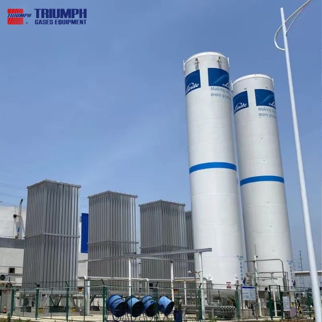
The cylindrical portion requires the inner diameter and straight-shell length. Inner diameter means the diameter across the vessel’s internal liquid-containing surface. Straight-shell length describes the cylindrical section between its defined end boundaries. Neither measurement should be replaced by the equipment’s shipping dimensions. Those external dimensions may include insulation, the outer jacket, supports, and fittings. Using them can overstate the volume available inside the inner vessel. Drawings should identify the dimensions clearly enough for another person to reproduce the calculation. If labels are ambiguous, obtain clarification before entering values into the worksheet.
For an ideal cylindrical section, use:
Cylindrical volume = (π × Internal diameter² ÷ 4) × Straight-shell length
Use meters for both measurements to calculate volume in cubic meters. This formula excludes the vessel’s curved end sections. Use meters for both measurements when calculating cubic meters. Convert millimeters before squaring the diameter. This step deserves attention because squared-unit errors can produce very large mistakes. The calculation covers only the cylindrical portion, so head volumes require separate treatment. It also assumes the dimensions describe the intended geometric basis. For detailed work, confirm whether dimensional records need correction for temperature or other specified conditions. A documented cryogenic liquid storage tank proposal should provide enough information to distinguish internal geometry from the external installation envelope.
Formed heads close the ends of many cylindrical storage vessels. Their curved profiles contribute internal volume beyond the straight-shell section. Common profiles include hemispherical, elliptical, and torispherical forms. Each has a different geometric relationship between diameter, depth, and volume. Therefore, selecting a head formula requires identifying the actual internal profile. A rounded appearance in a photograph cannot establish the correct geometry. The drawing should specify the head form and relevant dimensions. It should also show how straight flanges are included, preventing their volume from being omitted or counted twice.
For an ideal half-ellipsoid, internal volume can be expressed using its internal semiaxes. However, real formed heads may require the manufacturer’s geometric or certified capacity calculation. There is little value in using an elegant formula with uncertain dimensions. For preliminary estimates, identify every simplifying assumption beside the result. For final capacity work, use documentation reflecting the manufactured vessel. The combined head volume should then be added to the cylindrical-section volume. Check whether the supplier’s stated straight-shell length already includes any adjoining sections. This review is especially helpful when two calculations produce a modest but unexplained difference. Clear geometric boundaries prevent errors that can otherwise pass unnoticed into filling-volume and mass-capacity calculations.
Orientation affects how liquid level translates into partial volume. A horizontal cylindrical tank does not gain equal liquid volume for every equal height increase. Its cross-sectional area changes as the liquid surface rises. Near the bottom, a small depth increase adds relatively little volume. Around the middle, the same depth increase adds more volume. Curved heads further influence the complete relationship. Therefore, a level reading cannot usually be treated as an identical percentage of total capacity. This distinction matters when converting minimum operating level into retained inventory.
A vertical vessel’s straight cylindrical section has a simpler relationship between liquid height and volume. However, bottom geometry and internal details can still affect readings near its lower region. The complete tank should therefore use its appropriate calibration or capacity table. Such a table links measured level to volume on a defined basis. It may also include corrections relevant to the measurement system. Confirm whether an instrument displays height percentage or calculated volume percentage. These are different outputs even when both appear as percentages. Using the wrong interpretation can distort available inventory and delivery planning. The same care applies when estimating receiving space before a shipment. Tank-specific level conversion provides a stronger basis than assuming all percentage readings describe volume.
Several documents can describe the same tank from different perspectives. A general arrangement drawing focuses on equipment layout and installation dimensions. A vessel drawing provides geometry and construction details. A capacity certificate establishes volume on its stated basis. A calibration table connects measured level with inventory volume. Nameplate information identifies the equipment and its approved design information. These documents should support one another, but they do not necessarily contain identical fields. Understanding their purpose helps avoid choosing a convenient number from the wrong source.
When reviewing documents, first confirm they refer to the same supplied configuration. Check equipment identification, drawing revision, orientation, and any relevant modifications. Next, reconcile the quoted capacity against the documented inner-vessel volume. Investigate labels mixing radius and diameter or total length and straight-shell length. Also check whether nominal capacity describes a product family rather than the specific vessel. External dimensions can provide a useful reasonableness check, but they cannot establish exact internal volume. If discrepancies remain, request a written clarification from the manufacturer. Keep that clarification beside the calculation record. This creates a traceable basis for later purchasing, commissioning, and inventory discussions. It also reduces the chance that an early estimate becomes accepted as a verified equipment specification.
Tip: Use internal-vessel drawings and tank-specific capacity records before relying on dimensions from a sales listing.
Nominal capacity often describes a vessel size rather than its permitted liquid loading. The space above the liquid forms the vapor region required by the design. Filling limits account for applicable operating and reference conditions. They also reflect the installation’s approved basis for accommodating changes in the stored fluid. Consequently, geometric volume cannot automatically be used as the filling volume. Multiplying total internal space by LNG density may overstate permitted liquid inventory. The calculation must first establish the correct upper filling boundary for the actual service.
A further distinction exists between approved maximum filling and normal operating targets. A facility may plan deliveries to a lower target for operational reasons. If so, routine usable inventory should reflect that target rather than an unreachable maximum. Label both values clearly instead of switching between them during the calculation. Also verify whether the approved limit is expressed through volume, mass, or another defined loading relationship. Some terminology depends on reference temperatures or densities, requiring careful interpretation. A simple filling-fraction equation is useful only when its input matches the stated conditions. Buyers should ask suppliers to explain this basis in plain terms. That explanation connects the vessel’s nominal size with the amount of liquid actually permitted during operation.
The lower operating boundary has the same importance as the upper filling boundary. A tank may need retained liquid for its approved withdrawal arrangement. Pumped systems can have minimum-level requirements related to their installation and operating conditions. Other equipment arrangements may establish different lower limits. The relevant value should come from the design rather than a generic heel percentage. An assumption suitable for a preliminary study may not remain valid after equipment selection. Confirm it again when the withdrawal system and instrumentation are finalized.
To calculate the available working inventory, use the difference between upper and lower liquid inventories. If both limits are expressed as levels, convert each through the appropriate capacity table. Then apply density information suited to the calculation’s purpose. A simple preliminary estimate may use one consistent density. More detailed accounting may require different treatment as conditions change. Keep the lower limit visible in the final results table. Otherwise, a reviewer may confuse maximum stored mass with routinely available supply. The distinction also affects procurement comparisons. A larger nominal tank can provide less usable inventory than expected when its operating window is narrow. Comparing defined working inventories gives a clearer picture of what each proposed installation can deliver.
A contingency reserve protects production against events such as delayed deliveries. It differs from the liquid that must remain for equipment operation. The heel establishes a technical lower boundary. The contingency reserve establishes a business planning threshold above that boundary. Both affect routine scheduling, but they should remain separate quantities. If usable inventory already excludes the heel, subtracting it again understates available capacity. Likewise, adding several overlapping reserve allowances can oversize the installation without improving the underlying logistics plan.
A practical worksheet identifies each reserve and explains its purpose. For example, a delay allowance may represent additional consumption during an expected disruption. A separate growth allowance may address future production demand. These assumptions should not silently duplicate one another. Where reserves are stated as percentages, record their reference quantity. A percentage of geometric volume differs from a percentage of routine consumption. Converting allowances into a common mass basis makes overlap easier to identify. It also helps decision-makers understand the consequence of changing a planning assumption. More reserve generally means less inventory available for routine scheduling within an unchanged tank. Alternatively, preserving the same routine inventory requires additional capacity. Making that tradeoff explicit supports more disciplined storage planning.
LNG is a mixture, so its liquid density is not a universal constant. Its composition and thermodynamic condition influence the value used for calculations. Temperature and pressure therefore need a defined basis alongside composition. A density copied from an unrelated delivery can introduce avoidable uncertainty. Likewise, a rounded value from an introductory guide should not become an unquestioned accounting input. The appropriate property information depends on the calculation’s purpose. Early feasibility work may tolerate a clearly stated assumption. Final inventory or contractual measurement requires a more suitable verified basis.
Useful sources can include delivery documentation or a validated property calculation. Confirm whether the supplied density applies to loading, storage, or another reference condition. Do not mix a liquid volume measured under one condition with an incompatible density. For preliminary planning, document the assumed range and test how it affects results. This reveals whether uncertainty meaningfully changes the selected tank size. It also provides a better discussion point than arguing over one unexplained default value. If different liquid layers exist, a single density assumption may need additional assessment. The essential principle remains consistent: volume and density must describe compatible conditions. Once that relationship is clear, the LNG volume-to-mass conversion becomes straightforward and easier to verify.
An unchanged liquid volume can represent different masses when density changes. This does not mean the vessel’s geometric capacity has changed. It means the material occupying that volume has different properties. The distinction matters when procurement specifications mix cubic meters and tonnes. A tank described by volume cannot promise one fixed stored mass for every LNG condition. The calculation must show the assumed density and permitted liquid volume. This also explains why supplier filling-weight figures need their supporting assumptions.
The following table illustrates the effect using a hypothetical liquid volume. These values demonstrate arithmetic only and require verification for any real project.
Permitted liquid volume | Assumed LNG density | Calculated liquid mass |
|---|---|---|
90 m³ | 420 kg/m³ | 37,800 kg |
90 m³ | 450 kg/m³ | 40,500 kg |
90 m³ | 480 kg/m³ | 43,200 kg |
In every row, the liquid volume remains unchanged. Only the assumed density changes. The table should not be interpreted as an approved loading range for a particular tank. Actual permissible loading must satisfy the vessel’s documented requirements. For business planning, this sensitivity check helps explain uncertainty in stored tonnes. It also encourages consistent assumptions when comparing supplier proposals. If one proposal uses a higher density, its quoted mass may appear more attractive without offering additional volume. Normalizing the basis makes the comparison clearer and more useful.
Cubic meters of LNG describe liquid occupying physical tank space. Standard cubic meters of natural gas describe gas volume at defined reference conditions. These units therefore represent different measurement bases. A direct comparison without conversion can produce a major planning error. The gas reference temperature and pressure must be stated. Gas composition and the chosen property method also influence the conversion. Terms such as standard or normal should not be treated as self-explanatory. Their exact definitions can vary between commercial and technical documents.
Start by converting LNG liquid volume into mass:
LNG mass = LNG liquid volume × LNG liquid density
Then calculate the equivalent gas volume:
Gas volume at reference conditions = Gas mass ÷ Gas density at reference conditions
Use kilograms for mass and kg/m³ for density to obtain cubic meters. Specify the gas reference temperature and pressure.
This relationship requires compatible mass and composition assumptions. A rounded liquid-to-gas expansion factor can support rough explanations, but it is not a precise universal conversion. If demand is specified as energy, use an appropriate heating-value basis instead. Confirm whether that value represents higher or lower heating value. Mixing energy conventions can distort estimated consumption and storage duration. Recording these definitions beside the worksheet prevents a technically correct equation from producing an operationally misleading answer. It also makes supplier and customer calculations easier to reconcile.
Tip: State liquid conditions and gas reference conditions whenever converting between LNG volume, mass, and gas volume.
Consider a hypothetical vessel having a geometric internal volume of 100 cubic meters. For illustration, assume its permitted filling fraction is 0.90. Also assume LNG liquid density equals 450 kilograms per cubic meter. The minimum retained liquid inventory is assumed to be 4,500 kilograms. Daily demand is assumed to remain steady at 6,000 kilograms. These inputs create a simple calculation without claiming to describe a specific commercial tank. They are not recommended operating limits and require verification before project use. Actual filling conditions and equipment requirements can produce different values.
The example also needs clear boundaries around what it includes. It estimates liquid inventory and a simplified supply duration. It does not model changing liquid properties or total vapor-space inventory. It assumes no deliveries occur during the calculated period. It also excludes additional unaccounted material transfers and separate loss allowances. Demand is expressed directly as LNG-equivalent mass, avoiding an unexplained gas-volume conversion. These conditions keep the arithmetic easy to follow. They also show why calculation assumptions deserve the same attention as formulas. When applying the method to real equipment, replace every assumed value with an appropriate documented input. Keep the example separate from operating instructions so illustrative numbers cannot be mistaken for approved settings.
First, multiply geometric volume by the assumed filling fraction. This gives a permitted liquid volume of 90 cubic meters. Next, multiply that volume by the assumed LNG density. The calculated maximum liquid inventory becomes 40,500 kilograms. Subtract the assumed minimum retained inventory of 4,500 kilograms. The resulting usable liquid inventory is 36,000 kilograms. Finally, divide usable inventory by the assumed daily mass demand. Under the stated simplifications, estimated supply duration becomes six days. Each result follows directly from the previous stage.
Calculation stage | Illustrative calculation | Result |
|---|---|---|
Permitted liquid volume | 100 × 0.90 | 90 m³ |
Maximum liquid mass | 90 × 450 | 40,500 kg |
Usable liquid inventory | 40,500 − 4,500 | 36,000 kg |
Simplified supply duration | 36,000 ÷ 6,000 | 6 days |
Now add a separate hypothetical contingency reserve of 6,000 kilograms. Routine scheduled consumption would then have 30,000 kilograms available before reaching that reserve threshold. At the same demand, this represents five days of routine supply. The remaining reserve provides additional planning coverage above the retained heel. It does not change the vessel’s geometric capacity or maximum filling limit. This distinction helps separate equipment capability from scheduling policy. For actual operation, changing conditions and additional flows need assessment before relying on the stated duration. The table is a calculation demonstration rather than a complete operating model.
The hypothetical tank carries a 100-cubic-meter geometric rating, yet its usable inventory is smaller than that headline suggests. Its illustrative permitted filling volume is 90 cubic meters. Its usable mass is then reduced further by retained inventory. None of these differences indicate missing tank volume. They simply describe different capacity definitions applied to the same vessel. A buyer asking only for nominal capacity may therefore receive an incomplete answer to a supply-planning question. The useful result depends on the operating limits and property basis.
The supplied product references illustrate why this distinction matters. One listing presents capacity, filling ratio, and filling weight as separate fields. Their separation shows that a volume label and a mass figure are not interchangeable. However, individual listing values still require confirmation against the proposed equipment. They should not become universal calculation assumptions. When comparing quotations, request a short reconciliation from geometric volume to usable inventory. Ask the supplier to show the density basis and both operating boundaries. Then compare every proposal using consistent demand and reserve assumptions. This approach exposes differences hidden behind nominal capacity labels. It also makes the purchasing decision more closely reflect actual supply requirements rather than the largest advertised number.
Sizing begins with consumption information expressed on a consistent basis. Demand may arrive as tonnes per day, standard gas volume, or energy consumption. Convert these figures carefully before comparing them with liquid storage capacity. If demand uses gas volume, document its reference conditions and composition basis. If it uses energy, confirm the heating-value convention. The resulting mass demand should represent the consumers included within the project boundary. Avoid mixing production demand with additional flows already counted elsewhere. A clear consumption basis prevents errors from spreading through the sizing worksheet.
Next, examine how demand varies rather than relying only on its average. Daily operating schedules, production shifts, seasonal patterns, and shutdowns can affect inventory requirements. Peak flow and total consumption answer different design questions. Total consumption influences the amount of inventory required between deliveries. Peak flow influences whether withdrawal and gas-supply equipment can meet short-term demand. Both must be satisfied, but they require separate checks. Reviewing the complete cryogenic equipment range helps organize the required storage and downstream functions. The final equipment configuration should still follow verified project conditions. This connects tank sizing with the actual process rather than treating storage capacity as the only factor controlling supply performance.
A tank needs enough inventory to support consumption between planned deliveries. It also needs sufficient receiving space when the next shipment arrives. These requirements must be checked together. Selecting capacity from daily demand alone can overlook the practical delivery pattern. A shipment may exceed available receiving space even when the installation needs additional fuel. Conversely, a small shipment schedule may require more frequent deliveries than local logistics can support. Storage sizing should therefore reflect both supply and consumption.
Start by mapping expected delivery dates, shipment quantities, and demand between receipts. Calculate the inventory immediately before and after each planned delivery. Confirm both values remain within the defined operating window. Include realistic variations in timing and consumption where the project requires them. If deliveries involve different providers or transport arrangements, clarify the assumptions supporting each case. Also confirm whether partial deliveries are commercially and operationally practical. These details can affect the selected capacity as much as average demand. A larger vessel may provide scheduling flexibility, but its benefit should be evaluated against actual logistics. The objective is a workable inventory cycle rather than a nominal storage number. This makes the LNG storage capacity requirement easier to defend during purchasing and operational review.
Reserve planning should identify the specific uncertainty each allowance addresses. Minimum retained inventory protects the defined equipment operating boundary. A delivery-delay reserve supports consumption during a supply interruption. A growth allowance addresses anticipated increases in future demand. These quantities may all be relevant, but they should not overlap without explanation. Adding several unexplained percentages can create an inflated result. Removing all allowances can create a storage arrangement lacking practical resilience. The calculation should make each decision visible.
A useful approach expresses reserves in the same units as demand and inventory. A delay allowance can be converted into mass using the relevant consumption profile. The minimum heel remains a separate quantity below the intended operating window. If the sizing calculation already includes emergency consumption within its demand period, do not add it again. The same discipline applies when supplier proposals contain an existing capacity margin. Demand, delivery logistics, and retained reserves are connected sizing inputs in published LNG project studies. Their specific assumptions remain project-dependent rather than universal recommendations. Documenting each allowance helps decision-makers understand what additional capacity provides. It also makes future revisions easier when production schedules, supply routes, or delivery reliability change.
A time-based inventory balance tests whether the proposed tank supports realistic operation. Track opening inventory, receipts, consumption, and other relevant flows during each interval. The interval should be short enough to capture important changes. Daily steps may suit early planning, while some operations need finer detail. The general mass balance adds incoming material and subtracts material crossing outward through the defined boundary. Internal evaporation alone does not remove total mass from that boundary. Detailed liquid-level predictions require additional treatment of vapor and changing fluid properties.
A simplified balance can be written as:
\[ M_{k+1}=M_k+M_{\text{receipts}}-M_{\text{consumer supply}}-M_{\text{other exports}} \]
Use each physical flow once, avoiding duplicate deductions for recovered gas. Then compare predicted inventory against upper and lower operating constraints. Review delayed delivery, high consumption, and low-demand cases separately. A low-demand period may satisfy inventory needs while creating different pressure-management requirements. Therefore, inventory balance and thermal assessment should support one another. Record any assumptions about gas recovery or additional processing equipment. This validation turns a static capacity estimate into a more practical operating assessment. It also reveals when logistics changes could solve a problem more effectively than simply increasing nominal vessel size.
Tip: Check receiving space and minimum inventory across the delivery cycle, rather than comparing capacity against average demand alone.

A quotation should explain exactly what its capacity figure represents. Ask whether it describes geometric volume, permitted liquid filling, or usable operating inventory. If a mass is quoted, request the corresponding density and liquid-condition basis. If a supply duration is quoted, request the demand profile and reserve assumptions. These definitions allow the buyer to understand how the result was obtained. Without them, two proposals may appear comparable while describing different quantities. A concise reconciliation table is often more useful than a long list of promotional features.
Also confirm the intended storage medium and supplied configuration. A broad product family may cover several cryogenic services, but individual vessels remain application-specific. Similar names do not establish identical materials, pressure limits, or connection arrangements. When reviewing the tank series, identify the actual configuration proposed for LNG. Ask which documents will confirm its internal capacity and operating limits. Clarify whether the quoted system includes withdrawal equipment and related controls. These scope details affect the installation’s practical capability without necessarily changing geometric volume. A well-defined quotation links the headline capacity to the exact equipment being supplied. It also provides a stronger basis for technical review and later acceptance.
The capacity calculation should agree with the equipment’s controlled documentation. Begin by confirming the identity and revision of every drawing used. Compare internal diameter, cylindrical length, and head geometry against the stated volume. Then check whether internal structures or other documented allowances affect the result. A small difference may arise from different geometric assumptions or rounding. A large difference may indicate incorrect dimensions or incompatible capacity definitions. Neither should be dismissed without explanation when the result supports purchasing decisions.
The first supplied reference illustrates why online dimensional labels need careful review. Its technical table contains entries requiring clarification before reconstructing an internal-volume calculation. This does not establish the supplied vessel’s actual capacity independently. It shows why approved drawings provide a better calculation basis than an ambiguous listing. Ask the manufacturer to reconcile any conflicting radius, diameter, or volume information in writing. Keep the response alongside the final worksheet. Also verify whether later design changes altered the original capacity basis. Equipment identification and document control make that check possible. A clear record protects against using an early sales estimate after the project configuration has changed. It supports consistent information across purchasing, installation, and operation.
Correct arithmetic cannot compensate for incompatible inputs. Verify the units, conditions, and definitions attached to every important value. Liquid density must match the volume basis used for mass conversion. The filling fraction must apply to the specified loading conditions. Minimum inventory must reflect the proposed withdrawal arrangement. If it comes from a level reading, convert it using the appropriate tank table. Also identify whether instrument output represents physical height or calculated volume. These checks address common errors that simple formula reviews may miss.
Next, confirm the measurement information supports the required accuracy. A preliminary planning worksheet has different needs from custody transfer or detailed inventory accounting. Calibration records, measurement corrections, and property calculations should reflect that purpose. State any remaining uncertainty clearly beside the result. Where uncertainty could change equipment selection, test a reasonable range using documented assumptions. This creates a more informative review than presenting an estimate to excessive decimal places. The final worksheet should allow another reviewer to follow every conversion without guessing. It should also distinguish assumed inputs from verified equipment data. These practices make LNG storage tank capacity calculations more transparent and easier to update as better project information becomes available.
A preliminary calculation helps establish storage scale and compare possible configurations. It can identify approximate usable inventory and supply duration under stated assumptions. It can also reveal missing information before detailed equipment selection begins. However, it does not establish every condition required for the completed installation. Thermal behavior, pressure control, withdrawal performance, and measurement arrangements need additional assessment. The applicable design and installation requirements also remain relevant. These checks should develop alongside capacity calculations rather than being postponed until after equipment purchase.
For a practical procurement package, request a documented calculation basis and equipment scope. Include geometric capacity, permitted filling, property assumptions, minimum inventory, and the demand cases assessed. Ask the supplier to explain any limitations affecting the proposed operating window. Confirm how the selected equipment handles planned delivery and shutdown patterns. The resulting documentation should connect the vessel to its actual service conditions. It should also identify interfaces needing coordination with other equipment providers. This approach keeps preliminary estimates useful without treating them as final operating instructions. It supports a more reviewable decision and reduces uncertainty during later project stages. The most valuable calculation is one that explains its assumptions clearly enough for the responsible team to verify.
LNG storage tank capacity calculation connects geometric volume, permitted filling, liquid density, and minimum retained inventory. Usable inventory provides a clearer planning basis than nominal volume alone. Check it against demand, deliveries, and reserve requirements. Discuss these inputs with TRIUMPH to review suitable cryogenic tank configurations for your project.
A: Multiply LNG storage tank volume by the approved filling fraction; apply density, then subtract retained mass.
A: Usable LNG storage tank capacity excludes required retained inventory from maximum permitted inventory.
A: LNG storage tank mass calculations depend on composition and liquid conditions.
A: Check internal dimensions, head geometry, and capacity definitions.
A: Accurate LNG tank sizing helps avoid unnecessary capacity.


