
close
Choose Your Site
Global
Social Media


How does an LNG storage tank keep liquid cold while its surroundings remain warm? Insulation slows heat entry, while pressure controls manage vapor inside the tank. You’ll learn how filling, storage, and withdrawal work together to deliver LNG or supply gas.
The operating cycle begins when LNG arrives from a suitable transport or production system. Before transfer, the receiving installation must meet its approved preparation requirements. These may include cleanliness checks, drying, inerting, and controlled cooldown. Their purpose is to establish conditions suitable for introducing cryogenic liquid. Cooldown also reduces sudden temperature differences across piping, valves, and connected equipment. The exact sequence depends on the installation and its operating procedures. A tank already containing LNG may require different preparation from an empty, warm vessel. Therefore, filling should follow the approved system design rather than a general internet checklist.
During transfer, incoming liquid increases the stored inventory and changes conditions inside the vessel. It also interacts with vapor occupying the space above the liquid. Depending on incoming temperature and filling arrangement, vapor may condense or additional gas may form. Pressure behavior therefore reflects more than the rising liquid level alone. Some installations use vapor-return connections to manage displaced gas during delivery. Others rely on different arrangements defined by their process design. For a business evaluating equipment, the important question concerns the complete filling interface. The delivery connection, pressure compatibility, instrumentation, and vapor-handling arrangement must work together. A suitable tank cannot compensate for an incompatible transfer system.
Inside the tank, an inner container holds LNG at cryogenic temperature. Above the liquid surface, a vapor space contains natural gas. These two regions interact as heat enters and operating conditions change. The liquid-containing structure must tolerate its specified temperature, pressure, and mechanical loads. Material selection therefore considers more than ordinary corrosion resistance or wall thickness. Metals can behave differently when exposed to very low temperatures. Suitable materials retain the properties required for their intended cryogenic service. Supports and connections also accommodate movement as the inner container cools and contracts. This movement must remain compatible with the surrounding structure and connected piping.
The inner container’s role becomes clearer when separating storage from insulation. It provides the primary boundary containing the liquid under its design conditions. The surrounding insulation reduces heat transfer across that boundary. Meanwhile, the outer structure performs functions defined by the particular tank construction. Its presence does not automatically mean it provides equivalent liquid containment. Buyers should therefore examine the containment arrangement rather than relying on the phrase “double wall.” When reviewing a cryogenic liquid storage tank, confirm the proposed configuration’s approved medium and operating limits. Similar-looking vessels can have different materials, pressure ratings, and connection arrangements. Their appearance alone cannot establish suitability for LNG storage.
An LNG storage tank operates in surroundings much warmer than its contents. This temperature difference creates a continuous tendency for heat to enter. Insulation slows that transfer and helps preserve the stored liquid. However, no practical insulation system eliminates every heat-transfer path. Heat can enter through insulating materials, structural supports, piping connections, and other penetrations. The design must therefore address the complete assembly rather than the vessel walls alone. A well-insulated tank connected to poorly arranged piping may still experience avoidable thermal losses. This explains why tank insulation and transfer-line insulation should be considered together during project planning.
Different constructions reduce heat entry through different combinations of materials and structural details. Vacuum-insulated vessels use an evacuated space alongside suitable insulation. Other large storage designs use insulated spaces maintained under different conditions. These arrangements should not be treated as interchangeable technologies. Their performance depends on design, installation quality, operating conditions, and long-term condition. For procurement, asking only whether a tank “has insulation” provides little useful information. A better discussion covers the insulation method, expected thermal performance, and performance assessment conditions. It should also address inspection access and the supplier’s maintenance recommendations. These details help buyers understand how the tank preserves cold throughout its service life. They also provide a clearer basis for comparing proposals.
As heat reaches the stored LNG, some liquid can evaporate into the vapor space. This vapor is called boil-off gas, commonly shortened to BOG. Its formation is a normal consequence of storing a cryogenic liquid. The important issue is how the installation manages the resulting energy and vapor. In a closed pressurized vessel, heat input can raise internal energy and pressure. In other arrangements, vapor handling helps maintain pressure near its operating target. The exact response depends on liquid condition, vessel design, and connected equipment. Therefore, boil-off generation does not translate into one universal pressure-rise rate.
Boil-off gas management also affects how businesses interpret storage losses. Vapor formation does not necessarily mean gas immediately leaves the facility. An installation may consume, recover, compress, or otherwise manage that vapor. Product loss depends on the eventual destination of the gas. This distinction matters when comparing a supplier’s thermal-performance claims against actual operating costs. A quoted evaporation figure should include its test conditions and calculation basis. It should also identify whether it describes vapor generation or material released from the system. Buyers should avoid assuming that one percentage applies under every filling level and demand pattern. Understanding where vapor forms and where it goes gives a more useful picture of LNG storage performance.
Pressure control connects the storage vessel’s changing conditions to the needs of the wider installation. Heat ingress, filling, withdrawal, and gas consumption can all influence pressure. The control system responds through equipment selected for that particular process. Some systems direct available vapor toward a suitable gas consumer. Others use recovery equipment or compression to move gas elsewhere. Reliquefaction may be included where the project justifies and supports it. These options depend on the facility’s scale, available infrastructure, and operating requirements. They are not standard features automatically supplied with every LNG storage tank.
The operating objective also changes between installations. A pressurized supply vessel may need sufficient pressure for downstream delivery. A large storage facility may instead maintain pressure within a narrow, low-pressure operating range. Their control methods can therefore differ substantially despite storing the same product. For buyers, the practical task is defining operating conditions before selecting control equipment. Expected demand, shutdown periods, delivery frequency, and gas destination all affect the solution. A proposal should explain how pressure behaves during normal consumption and extended low demand. It should also distinguish routine regulation from protective functions. Without this explanation, a list of valves and instruments reveals little about actual system behavior. The process description should show how those components work together.
LNG leaves the tank through an arrangement matched to the receiving process. Certain pressurized installations use tank pressure to move liquid downstream. Other installations use pumps to provide the required flow and pressure. The appropriate method depends on the storage configuration and delivery requirements. Available pressure must account for downstream conditions and losses along the transfer route. Pumped systems also require suitable inlet conditions and equipment arrangements. Therefore, withdrawal performance cannot be judged from tank capacity alone. The vessel, transfer equipment, and receiving process form one connected system.
The next destination determines whether LNG remains liquid or becomes gas. A liquid-transfer application sends it toward another suitable cryogenic vessel or process. A gas-supply installation routes it through a vaporizer and associated regulation equipment. The vaporizer supplies heat, allowing the liquid to change into gas. This function is separate from preserving LNG inside the storage vessel. Confusing these roles can lead to incomplete equipment specifications. Businesses should define the required delivery state before requesting a quotation. They should also identify expected flow variation and downstream pressure requirements. Reviewing the complete cryogenic equipment range can help organize these connected equipment needs. The final configuration still requires confirmation against the project’s actual operating conditions.
Tip: Ask suppliers to describe the complete filling, storage, vapor-management, and delivery cycle before comparing individual components.

A vacuum-insulated vessel typically places its inner container inside an outer jacket. The space between them is evacuated to reduce gas-mediated heat transfer. Suitable insulation also addresses heat radiation and remaining thermal paths. Depending on the design, this may involve multilayer insulation or other insulating materials. The vacuum and insulation work together rather than serving identical functions. Structural supports remain necessary because the inner container must carry its operating loads. Those supports create thermal paths that engineers must also control. Piping penetrations introduce additional design considerations because they connect cold equipment with warmer surroundings.
Vacuum quality is important, but a single vacuum reading does not describe the complete system. Thermal performance also depends on insulation arrangement, support design, penetrations, and installation condition. Maintaining the outer jacket and its associated connections helps preserve the intended environment. If insulation performance changes, heat ingress and operating pressure trends may also change. However, pressure behavior alone cannot prove a specific vacuum defect. Filling history, ambient conditions, and demand must also be considered. Buyers should request the manufacturer’s performance basis and inspection recommendations. They should also clarify how vacuum condition is checked without disturbing normal operation. This information supports meaningful maintenance planning and avoids treating “high vacuum” as a complete technical specification. Vacuum-insulated LNG storage is established technology, but its performance remains configuration-dependent.
Large flat-bottomed LNG tanks can use insulating arrangements different from vacuum-jacketed pressure vessels. Expanded perlite may occupy an insulated space surrounding the inner tank. Other insulation materials and details address the roof, base, and structural interfaces. Each part contributes to limiting heat transfer across the complete storage structure. Some designs maintain nitrogen in the insulation space under specified conditions. This environment should not be confused with an evacuated annulus. The presence of two walls therefore does not prove that vacuum insulation is used. Understanding this distinction prevents misleading comparisons between fundamentally different tank constructions.
The supplied large-tank reference describes perlite insulation combined with nitrogen. Its description provides a construction example rather than a universal LNG storage specification. Buyers should ask how the complete insulation system is arranged and monitored. Relevant questions include moisture control, insulation-space conditions, and long-term settlement considerations. The answers should relate directly to the proposed tank configuration. Comparing only insulation material names can hide important differences in implementation. Two proposals mentioning perlite may still use different structural arrangements and operating assumptions. Project documents should explain the insulation system’s boundaries and intended condition. They should also identify which inspection and maintenance activities preserve its performance. This approach gives procurement teams a clearer understanding of how large storage tanks limit heat entry.
An LNG storage tank generally receives natural gas already converted into liquid upstream. Its insulation preserves that condition by slowing incoming heat. Insulation itself does not remove heat like an operating refrigeration system. This distinction explains why even an efficient tank needs vapor-management provisions. Over time, unavoidable heat input changes the stored fluid’s condition. Depending on the installation, the system accommodates that change through pressure capacity, gas use, or other equipment. Storage therefore depends on thermal performance and operating strategy working together. Neither element should be evaluated independently when specifying a complete installation.
This principle also explains why “long-term storage” requires a defined operating basis. The phrase does not establish an unlimited period without pressure changes or gas handling. Storage duration depends on starting conditions, allowable pressure range, inventory, and ongoing demand. A facility consuming gas regularly behaves differently from one experiencing an extended shutdown. Additional recovery or refrigeration equipment may change that behavior where included. Buyers should therefore request assumptions behind any holding-time claim. The supplier should explain initial liquid conditions and the criterion ending the stated holding period. A clear definition makes the claim useful for operational planning. Without those details, the same phrase may describe very different situations. Understanding what insulation actually does helps businesses ask better questions and avoid unrealistic storage expectations.
Tip: Double-wall construction does not automatically identify the insulation method or the outer structure’s containment capability.
Liquid LNG and its vapor respond together when energy enters the vessel. Part of that energy may support evaporation, while temperatures and pressure also change. The response depends on composition and the fluid’s starting condition. LNG is a mixture, so its behavior cannot always be reduced to pure-methane assumptions. Pressure and temperature readings must therefore be interpreted within the actual operating context. A liquid temperature value alone does not establish the tank’s pressure condition. Likewise, one pressure reading does not explain how much heat entered or gas formed. These measurements become more useful when considered alongside inventory and recent operating events.
The vessel’s pressure regime determines how these changes are accommodated. A pressurized storage vessel can accept pressure increases within its approved operating range. A large low-pressure tank generally depends more directly on its connected vapor-management system. Neither arrangement removes the need for defined pressure limits and protective equipment. For business planning, the relevant issue is the available operating envelope. Buyers should understand normal pressure, permitted variation, and the conditions requiring intervention. These values should come from approved design documents rather than generic industry examples. A clear operating envelope helps connect thermal behavior with supply reliability. It also prevents incorrect comparisons between equipment intended for substantially different pressure conditions.
Normal boil-off gas management gives generated vapor an appropriate destination. Depending on the installation, gas may support a compatible downstream consumer. Other systems compress it, return it through suitable infrastructure, or recover it through additional processing. Some projects include reliquefaction to convert recovered gas back into liquid. Each approach requires equipment and operating conditions suited to the selected process. The available gas flow and downstream demand must also remain compatible. Consequently, a vapor outlet alone does not establish a complete BOG-management solution. The destination, control arrangement, and operating limits must also be defined. Different gas-management technologies are used according to storage-system requirements.
An important procurement question concerns what happens when the usual gas consumer stops. A system operating comfortably during production may behave differently during weekends or maintenance shutdowns. The project therefore needs a defined response to low-demand periods. That response may involve storage pressure capacity or other installed management equipment. It must be evaluated against the actual installation rather than assumed from another project. Businesses should provide realistic demand profiles when discussing equipment selection. Average daily consumption alone can hide long periods without withdrawal. Understanding those periods helps suppliers assess vapor handling and storage behavior. It also supports more reliable comparisons between proposals offering different levels of process integration.
Some pressurized LNG supply systems need help maintaining delivery pressure during withdrawal. A pressure-building circuit can provide this function where the design requires it. Typically, a small liquid stream passes through a dedicated vaporizing section. The resulting gas returns to the vessel’s vapor space through a controlled arrangement. This process adds vapor and energy to support tank pressure. It helps maintain the pressure difference needed for the intended delivery process. The circuit operates according to the vessel’s approved controls and pressure limits. It is not a feature that should be assumed for every LNG tank.
Pressure building and boil-off management address different operating needs. Pressure building supports pressure when delivery conditions would otherwise cause it to fall. Boil-off management handles vapor and energy associated with heat ingress and other process effects. Their functions must remain coordinated within the complete control strategy. An incorrectly specified arrangement can undermine stable delivery or create unnecessary pressure cycling. Procurement teams should therefore ask when the pressure-building circuit operates and why it is required. They should also identify its expected contribution under maximum demand. Supplier documentation should show its relationship with regulators, withdrawal lines, and protective devices. This explanation is more valuable than simply listing a pressure-building vaporizer among supplied components. It connects the equipment directly to the installation’s required performance.
Pressure-relief devices protect the installation against specified overpressure conditions. They serve a different purpose from controls managing routine operation. A normal pressure-control system aims to keep conditions inside the intended operating range. Relief equipment provides an additional protective function when defined conditions occur. Its selection and installation must follow the applicable engineering requirements. Discharge routing also matters because released gas requires appropriate handling. These details belong in the approved system design and supporting documentation. They should never be inferred from a general explanation of LNG tank operation.
This distinction helps businesses evaluate claims about storage efficiency and emissions. Routine pressure management should not automatically be described as continuous atmospheric venting. Where vapor can be used or recovered, that destination affects actual material losses. Equally, the presence of relief valves does not prove that everyday gas management is adequate. Buyers should ask suppliers to explain both functions separately. The process description should identify normal operating actions and independent protective responses. It should also address foreseeable low-demand and interrupted-service conditions. Operating personnel need clear instructions for abnormal events and equipment faults. Those instructions must come from the responsible manufacturer and facility procedures. A well-documented system makes the difference between routine control and backup protection understandable throughout procurement, commissioning, and operation.
Tip: Include shutdown periods and minimum gas demand when asking suppliers to assess pressure-control requirements.
Filling introduces more than additional liquid volume into the vessel. It also introduces LNG carrying its own temperature, pressure history, and composition. Those properties influence how the incoming liquid interacts with existing inventory. Vapor displacement can affect pressure as the liquid level rises. Flashing may occur when liquid encounters conditions different from its previous state. Conversely, colder incoming liquid may condense some existing vapor under suitable circumstances. The resulting pressure trend therefore depends on several interacting factors. Assuming pressure always rises identically during every delivery oversimplifies the filling process.
The filling connection and distribution arrangement also influence internal behavior. Certain installations provide different filling routes for specific operating requirements. Their use depends on the approved design and the condition of both liquid inventories. Large tanks may require particular attention to density differences and liquid distribution. Smaller pressure vessels have their own transfer and pressure-management requirements. Businesses should therefore confirm compatibility between delivery equipment and receiving storage. The discussion should cover connection arrangements, allowable conditions, vapor handling, and transfer monitoring. It should also establish responsibility for the interface between equipment suppliers. A clear interface specification reduces uncertainty during commissioning and routine deliveries. It helps ensure that the proposed LNG tank filling process matches the installation’s actual logistics and operating pattern.
A storage vessel’s total internal volume differs from its permitted liquid inventory. The unfilled region above the liquid provides vapor space required by the design. It accommodates vapor and supports the vessel’s intended operating behavior. Filling limits also account for relevant liquid expansion and operating conditions. Consequently, a nominal capacity figure does not directly describe usable LNG inventory. The approved filling limit must be established for the particular vessel and service. It should not be replaced by a percentage borrowed from another tank. Applicable requirements and manufacturer documentation define the correct operating basis.
This distinction has practical consequences for purchasing and delivery planning. A buyer estimating supply duration from total vessel volume may overestimate available inventory. Some inventory may also remain unavailable because of minimum operating-level requirements. Pump operation, process continuity, and delivery scheduling can influence that minimum. The useful storage window therefore lies between defined upper and lower operating limits. Procurement documents should state whether capacity means geometric volume, permitted filling volume, or usable inventory. Suppliers should use consistent definitions when presenting competing proposals. Businesses can then compare storage duration using the same demand assumptions. Clear capacity terminology also improves communication with delivery providers and operating teams. It connects equipment size with real supply capability rather than relying on a single headline volume.
Withdrawal equipment determines how stored LNG reaches its next destination. In suitable pressure-driven systems, vessel pressure provides the force needed for liquid movement. The available pressure difference must overcome downstream pressure and transfer-line losses. In pumped systems, the pump supplies the required increase in pressure. Its selection depends on flow requirements, liquid condition, and installation arrangement. Neither approach can be judged independently from the receiving process. A system requiring intermittent transfer may differ from one supporting continuous gas supply. The operating envelope must therefore cover expected variations rather than one nominal flow point.
Connected piping and valves also affect withdrawal quality and reliability. Insulation limits unwanted heat entry along the transfer route. Suitable isolation arrangements support operation and approved maintenance activities. Pipe routing, elevation changes, and pressure losses influence the overall transfer conditions. Procurement teams should ask for a defined boundary between tank supply and downstream equipment. This boundary should identify the conditions guaranteed at the agreed delivery point. Flow, pressure, and liquid condition should be considered together. Suppliers should also explain the equipment’s behavior at low inventory and variable demand. These questions help reveal whether the proposed arrangement supports the intended process. They make comparisons more meaningful than simply checking whether a pump or liquid outlet is included.
A vaporizer adds heat to withdrawn LNG so it can become usable gas. Its energy source depends on the selected equipment and installation. Some designs draw heat from ambient air, while others use different heating arrangements. The vaporizer’s required duty depends on flow and inlet conditions. Its outlet must meet the needs of downstream regulation and consumption equipment. Therefore, gas-delivery performance involves more than the storage vessel’s available inventory. A sufficiently large tank cannot compensate for inadequate vaporization capacity. The complete system must support the required flow under the specified environmental conditions.
The separation between storage and vaporization also helps explain common supply problems. Stored liquid may remain available while downstream gas capacity becomes restricted. Conversely, suitable vaporization equipment cannot deliver gas after usable liquid inventory is exhausted. Businesses should assess these functions together when defining supply reliability. Relevant questions include peak demand, demand duration, ambient conditions, and required outlet temperature. The project may also need a defined strategy for standby equipment or interrupted service. These choices depend on production requirements rather than tank volume alone. Reviewing the storage-to-gas pathway makes each equipment responsibility clearer. It also provides a practical basis for discussing integrated solutions across the tank series and associated equipment.
The inner vessel directly contains the stored LNG under its specified conditions. The outer structure performs functions determined by the overall construction. In a vacuum-jacketed vessel, it helps maintain the evacuated insulation space. It also protects internal insulation and supports the assembled equipment arrangement. In other tank designs, the outer structure may have additional containment responsibilities. Those responsibilities depend on the specified containment concept and engineering details. An outer wall should therefore never be assumed to hold the complete liquid inventory. Its actual capability must be established from the design.
Understanding these separate roles improves technical discussions during purchasing. Terms such as double wall, double containment, and full containment describe different concepts. They should not be used interchangeably without checking their technical meaning. Buyers should request a clear description of the primary and secondary boundaries. Relevant documentation should explain liquid containment, vapor containment, insulation, and structural support. It should also identify the responsibilities of foundations and connected civil works. These details become especially important when comparing packaged vessels against large site-built storage. Their installation boundaries can differ substantially despite sharing a cryogenic storage purpose. A component-level explanation helps business teams understand what the supplier actually provides. It also reduces ambiguity when engineering, procurement, and construction responsibilities are divided among different organizations.
An LNG tank monitoring system provides information about changing storage conditions. Pressure readings show the state of the vapor space at the measurement point. Level readings indicate inventory according to the installed measurement method. Temperature readings help describe the fluid and selected equipment locations. Each instrument answers a different question about operation. Their readings become more useful when viewed together across time. A pressure increase following a delivery may have a different explanation from an unexplained idle-period rise. Likewise, changing level can reflect withdrawal, filling, or other measurement considerations.
Businesses should therefore assess monitoring as a connected information system. Instrument location, measurement range, and intended use all influence interpretation. A display showing several values does not automatically provide complete operational insight. The facility also needs defined limits, reliable records, and appropriate operator understanding. Where remote monitoring is proposed, its actual functions should be confirmed. Data transmission alone does not establish automatic control or independent protection. Procurement discussions should identify which measurements support inventory management and which support operating decisions. They should also clarify calibration requirements and maintenance access. Clear documentation helps operators distinguish expected changes from conditions requiring investigation. It also supports more productive conversations with the supplier when equipment behavior changes over time.
Valves and piping create the pathways connecting storage with the wider process. Filling lines bring LNG into the vessel under controlled conditions. Withdrawal lines carry liquid toward transfer equipment or downstream vaporization. Vapor connections support the functions assigned by the process design. Pressure-building circuits, where present, introduce additional liquid and gas paths. Each connection has a defined purpose that should remain clear in documentation. Similar-looking valves may serve different operating or protective functions. Therefore, understanding the system requires more than identifying individual components by appearance.
A piping and instrumentation diagram helps explain these relationships. It shows equipment boundaries, flow paths, instruments, and relevant control connections. For buyers, this drawing provides a useful bridge between commercial descriptions and actual operation. It helps establish whether quoted equipment covers the required process functions. It also identifies interfaces needing coordination with other suppliers. During review, businesses should ask which paths operate during filling, storage, and withdrawal. They should also clarify how isolation and protective arrangements are incorporated. Any trapped-liquid sections require appropriate consideration within the engineered design. These details should be handled through approved engineering rather than improvised field changes. A clear flow-path explanation makes commissioning discussions more efficient and supports consistent operating documentation.
Monitoring tells operators what the installation is experiencing. Automatic control changes equipment behavior to maintain defined operating conditions. Protective systems respond when specified abnormal conditions arise. These functions are related, but they are not interchangeable. An instrument displaying pressure does not necessarily control it. A normal regulating valve does not automatically provide an independent shutdown function. Likewise, an alarm requires an appropriate response arrangement to serve its intended purpose. Understanding these distinctions helps businesses evaluate what a proposed control package actually delivers.
The required functions depend on the installation’s engineering and operating basis. Equipment may include alarms, interlocks, shutdown actions, and independent mechanical protection. Their selection should reflect the system’s applicable requirements and assessed operating conditions. Procurement teams should request a functional description covering normal and abnormal states. It should explain what the system detects and how it responds. The description should also identify which actions require operator involvement. Communication failures, interrupted power, and unavailable downstream equipment may need defined responses. Those responses must be established for the actual project. Clear documentation supports testing during commissioning and later maintenance. It also prevents remote monitoring features from being mistaken for a complete protection strategy. Ultimately, the equipment’s behavior matters more than the number of control features listed.
Tip: Request a process diagram and control description showing each component’s role during normal operation and shutdown.
Vacuum-insulated pressure vessels combine cryogenic storage with a defined pressure-containing design. Their inner vessels must satisfy the requirements of the proposed service. The outer jackets support the insulation environment and associated structural functions. These vessels may be arranged vertically or horizontally according to project needs. Their operating behavior depends on pressure limits, filling conditions, and connected equipment. Some installations use vessel pressure to assist liquid delivery. Others incorporate pumps or different supply arrangements. The correct configuration follows the process requirements rather than the vessel’s orientation alone.
These systems should be assessed using their approved operating envelope. Maximum allowable pressure, normal pressure, and delivery pressure describe different considerations. Buyers should understand how the proposed installation moves between its normal operating states. They should also ask how reduced consumption affects available holding time. The pressure-control arrangement must suit the actual demand profile. A pressure vessel suitable for one gas application may need different configuration for another. This also applies when reviewing a micro bulk tank for compact cryogenic storage. Its general equipment category does not establish LNG compatibility. Confirm the proposed medium, materials, approvals, and operating conditions with the supplier. These checks connect the selected vessel directly to its intended service.
Large flat-bottomed LNG tanks serve storage requirements different from many packaged pressure vessels. Their structures, insulation systems, and supporting infrastructure reflect the scale of stored inventory. They commonly operate at much lower pressure than pressurized cryogenic vessels. Their operating philosophy therefore depends on suitable vapor handling and liquid-transfer arrangements. The tank works as part of a facility rather than an isolated storage component. Foundations, process piping, instrumentation, and other systems influence the complete installation. These interfaces must be defined clearly during project development.
The supplied large-tank example illustrates a flat-bottomed construction using perlite insulation and nitrogen. Its specifications should remain associated with that particular offering. They should not be transferred to vacuum-insulated tanks or every large LNG installation. For buyers, the useful comparison concerns operating functions rather than outward appearance. How does the tank limit heat entry? Where does generated vapor go? How is liquid transferred toward downstream equipment? The answers reveal the equipment and infrastructure required around the storage structure. They also show why different designs cannot share identical maintenance or operating assumptions. A project’s capacity, logistics, and demand pattern shape the final arrangement. Understanding those relationships helps buyers assess complete proposals instead of comparing nominal volume alone.
Different LNG tank designs share the need to contain cold liquid and manage incoming heat. Their methods for accomplishing those tasks can differ significantly. A vacuum-jacketed pressure vessel uses a different operating basis from a large low-pressure storage tank. The surrounding equipment must reflect that difference. Pressure control, vapor handling, and liquid withdrawal should all follow the selected design. A component common in one arrangement may be unnecessary or unsuitable in another. Therefore, copying an equipment list from a different installation can create an incomplete specification.
A useful comparison begins with required performance rather than preferred construction terminology. Define usable inventory, delivery conditions, demand variation, and expected idle periods. Then examine how each proposal satisfies those requirements. Ask suppliers to state assumptions behind thermal performance and holding-time claims. Confirm which equipment belongs inside the quotation and which remains a site responsibility. This comparison also reveals differences in commissioning and maintenance requirements. A lower component count does not necessarily mean a simpler complete installation. Some functions may instead be assigned to equipment outside the supplier’s scope. Comparing operating responsibilities provides a more accurate view of the project. The table below summarizes common distinctions, while individual designs still require verification.
Operating feature | Vacuum-insulated pressure vessel | Large flat-bottomed LNG tank |
|---|---|---|
Insulation arrangement | Evacuated jacket plus suitable insulation | Engineered wall, roof, and base insulation |
Pressure regime | Defined pressurized operating range | Commonly operates closer to atmospheric pressure |
Vapor management | Depends on demand and installed controls | Typically integrated into facility vapor-handling systems |
Liquid withdrawal | Pressure-driven or pump-assisted | Commonly pump-assisted |
Project integration | Often supplied as packaged equipment | Usually requires substantial site integration |
Essential confirmation | Medium compatibility and operating envelope | Containment concept and facility interfaces |
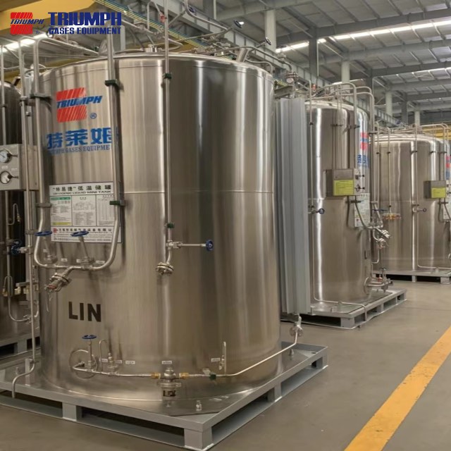
Insulation performance can change as equipment ages or operating conditions vary. Increased heat entry may influence vapor generation and pressure behavior. In vacuum-insulated equipment, changes in the insulation-space condition can affect thermal performance. Other tank constructions have their own inspection and maintenance concerns. The relevant indicators depend on the equipment’s design and service history. Unexpected cold areas on an outer surface may justify investigation. However, local cooling near known cold connections can have a different explanation. Observations must therefore be interpreted against the manufacturer’s expected operating behavior.
A systematic review considers several indicators rather than one isolated symptom. Pressure trends, ambient conditions, delivery history, and demand provide useful context. The condition of piping insulation and connected equipment also matters. A storage tank may be blamed for losses originating elsewhere in the installation. Maintenance teams should follow approved inspection methods and escalation procedures. They should avoid assuming that every pressure increase proves insulation failure. For business owners, keeping baseline operating records makes later changes easier to assess. The baseline should reflect known equipment condition and normal service. It provides a practical reference when discussing performance concerns with qualified personnel. Manufacturer troubleshooting guidance similarly treats pressure trends and external observations as investigation inputs rather than standalone conclusions.
Storage duration depends on how the installation operates between deliveries and withdrawals. A system serving regular demand removes material and energy through its intended process. An idle system experiences different conditions because heat can continue entering without comparable withdrawal. Pressure may therefore behave differently during production and shutdown periods. The available response depends on the vessel’s pressure range and installed gas-management equipment. A tank that performs well during continuous operation may need additional consideration during extended low demand. This is why average consumption alone does not describe the complete storage requirement.
Holding time should always be associated with stated starting conditions and an endpoint. Relevant factors include liquid condition, inventory, ambient exposure, and allowable pressure change. The definition should also explain whether gas use or recovery continues during the period. Without this basis, holding-time comparisons can be misleading. Businesses should provide realistic weekly and seasonal operating patterns during equipment selection. Planned maintenance shutdowns and irregular delivery schedules also deserve attention. Suppliers can then assess the proposed equipment against recognizable operating cases. This approach helps connect storage sizing with actual business continuity needs. It also avoids assuming that a larger vessel automatically solves every low-demand pressure issue. Storage capacity and operating strategy must remain coordinated.
Large LNG inventories can develop internal differences in temperature, composition, and density. Incoming LNG may not immediately mix uniformly with the liquid already stored. Under certain conditions, distinct liquid layers can form. This condition is called stratification. Over time, heat input and composition changes can alter the relationship between those layers. A rapid mixing event may then produce a substantial increase in vapor generation. This phenomenon is known as rollover. It differs from the ordinary gradual evaporation discussed earlier. Industry guidance addresses stratification and rollover as specific LNG storage concerns.
The practical implication is that pressure alone cannot describe every important tank condition. Large-storage management may also require information about liquid properties and their distribution. Delivery history helps explain how the existing inventory developed. The appropriate monitoring and management arrangements depend on the facility’s approved design. They may involve suitable measurements and defined filling or circulation strategies. These measures require project-specific engineering and operating procedures. Buyers should ask how the proposed installation addresses differences between incoming and existing LNG. They should also confirm what information operators need before accepting a delivery. This discussion keeps attention on liquid behavior rather than treating the tank as a uniform container. It supports a more complete understanding of large-scale LNG storage operation.
Operating records connect individual measurements with the events affecting the tank. Useful information includes pressure, level, relevant temperatures, deliveries, and withdrawals. Demand interruptions and equipment maintenance also provide important context. Recorded together, these details help explain changes across operating cycles. A pressure rise during an extended shutdown may follow an expected pattern. A similar rise during normal demand may require a different investigation. Without event records, those situations can appear almost identical. Consistent documentation therefore improves the value of the installed monitoring system.
For businesses, records also support communication across operations, maintenance, and equipment suppliers. They help establish when a change began and what happened beforehand. This reduces reliance on memory when reviewing unusual performance. The objective is not collecting every possible value without purpose. It is maintaining information relevant to the installation’s operating decisions. Measurement frequency and review practices should follow the facility’s approved requirements. Baseline trends can then support maintenance planning and supplier discussions. When developing a project with TRIUMPH, provide actual demand patterns and expected delivery arrangements. Ask the supplier to confirm the proposed configuration against those conditions. A documented operating basis makes technical discussions clearer throughout equipment selection and service. It also links tank performance to the production needs the installation must support.
Tip: Compare operating trends under similar inventory, demand, and ambient conditions before drawing conclusions about performance changes.
An LNG storage tank combines insulation, containment, pressure control, and liquid withdrawal to preserve LNG and support dependable delivery. Matching these systems to demand helps businesses manage vapor generation and maintain consistent gas supply. TRIUMPH offers cryogenic storage tanks and related equipment to support coordinated storage and delivery systems. Discuss your operating conditions with its team to identify a suitable configuration for your project.
A: An LNG storage tank limits heat entry, manages vapor pressure, and supplies liquid downstream.
A: Heat entering an LNG storage tank causes evaporation, producing boil-off gas.
A: LNG storage tank costs depend on insulation performance, demand, and vapor management.
A: LNG tanks use different insulation methods, pressure ranges, and withdrawal arrangements.
A: Heat ingress, filling conditions, or reduced demand can raise LNG tank pressure.


